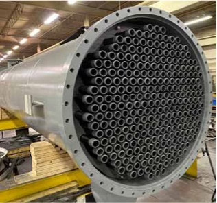
Tubes on this graphite heat exchanger are replaced in-house after excessive fouling resulted in tube breakage during service at a phosphoric acid plant.
As seen originally published in World Fertilizer Magazine.
In the concentration of phosphoric acid, the evaporator is a critical controlling component for the production rate. Optimizing graphite evaporator efficiency and operating procedures will help ensure maximum productivity within the evaporator and avoid unnecessary downtime and unanticipated plant shutdowns. Regardless of which material is used in the construction of an evaporator, the overall performance is dictated by the following basic heat transfer equation:
Q = A x U x LMTD
Where,
Q = Amount of heat transferred
A = Heat transfer area of the evaporator U = Overall heat transfer coefficient LMTD = Log mean temperature difference
In the case of the phosphoric acid shell and tube evaporator, the objective is to optimise the amount of heat transferred from steam flowing through the shell to the acid flowing counterflow through the tubes, using a fixed heat transfer area, A. To accomplish this, one must consider practical ways to maximize the overall heat transfer coefficient, U, and the temperature difference, LMTD. The U-value is defined as the reciprocal of the overall resistance to heat transfer from the shell or steam side of the unit, across the tube and into the process side acid stream. It has four components and is defined by the following formula:
![]()
Where,
L = Tube wall thickness
K = Thermal conductivity of tube material hi = Tube inside film coefficient
ho = Tube outside film coefficient F = Fouling factor
In order to maximize the U-value, the tube thermal conductivity and tube outside and inside film coefficients should be maximized, while the process fouling should be minimized.

U-value vs tube velocity.
Though the tube thermal conductivity does have an important role in a tube’s ability to resist thermal stress damage and fatigue failure, it plays a minor role in the overall heat transfer efficiency in that it typically only accounts for about 3% of the overall resistance. Even a significant increase in the tube’s thermal conductivity will have only a minor effect on the overall U-value. Therefore, the other three components; outside and inside film coefficients and fouling, will be the focus.
In a properly designed steam system where saturated steam is utilized, the outside film coefficient is relatively high, typically 4 – 6 times greater than the inside film coefficient. This results in the outside film coefficient being a smaller component to the overall resistance. However, there are commonly found practices in steam operating systems that can reduce the outside film coefficient drastically. Included in these practices is the use of superheated steam and poor condensate removal. Not only do these two practices have a dramatic effect on evaporator performance, but they can also cause severe mechanical damage in the evaporator based on creating either high mechanical and thermal stresses or dangerous vibration loading.
Superheated steam is normally a result of poor control of the desuperheater. Desuperheating is the process in which superheated steam is restored to its saturated state. There are at least two issues with using superheated steam versus saturated steam that need to be considered. First, in the superheated state, steam has an extremely low film coefficient. Until the saturated steam temperature is met within the tubes, the portion of tube subjected to the superheated steam is basically lost heat transfer area.
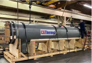
This large 42″ graphite shell and tube heat exchanger is ready to ship after being refurbished by our in-house technicians.
Depending upon the degree of superheating, this could result in 20% lost heat transfer area. Secondly, the specific volume of superheated steam is much greater than saturated steam. This results in much higher velocity in the shell than what it was designed for. This can lead to a dangerous vibration situation. Lastly, the higher steam temperature leads to higher tube wall temperature. The higher tube wall temperature can increase fouling rates, change the nature of the fouling, and increase thermal stresses across the tube wall.
Condensate build up in the shell is normally a result of poor condensate removal or the use of the incorrect trap. From a thermal performance perspective, the accumulation of condensate in the unit reduces the film coefficient for the portion of tube length subjected to the condensate by a factor of three to four times. Poor condensate removal not only has an affect on the heat transfer rate, but also creates a dangerous situation where severe water damage can occur as live steam is fed into the unit. In this situation there is a strong possibility of violent tube vibration during system start-up.
Proper connection sizes and pipe arrangements are important to avoid conditions that will promote condensate entrainment. Additionally, a pumped steam trap should be employed to ensure proper removal. It is very important to avoid condensate buildup on the shell side of the unit at all times.
Now we will look at a very important component, the inside film coefficient.
In properly operating steam evaporator systems, the tube inside film coefficient can account for as much as 50% of the total heat transfer resistance. Maximizing this value can have a dramatic positive effect on the overall heat transfer coefficient. It is a function of the tube dimensions, fluid physical properties, and the flow rate or velocity, with velocity being the most controllable and having the greatest influence.
Historically, up until about 30 years ago, the maximum tube side design velocity was in graphite evaporators in the 3 FPS (feet per second) range. The thought being that anything higher would cause erosion in the tube. The current design practice is to design for 10 FPS velocity, enhancing the turbulent flow at the tube wall. The higher velocity does not erode the graphite tube and results in reduced fouling rates and higher heat transfer efficiency. As shown in Figure 1, an increase in fluid velocity from 2 to 10 FPS increases the U-value by more than 50%.
It is recommended that the tube side velocity be increased to a practical limit, based on installed pumps and acceptable system pressure drop limitations, keeping in mind that pressure drop is a squared function of the velocity.
Maintaining proper pressure level on the process side of the evaporator is a critical aspect of ensuring the overall effectiveness of the heat transfer process. The importance of preventing the acid within the system from vaporizing within the tube cannot be overstated. Vaporization is detrimental to the inside film coefficient for several reasons. Firstly, when acid vaporizes, it introduces a phase change within the tube, leading to a significant reduction in heat transfer efficiency. The latent heat associated with vaporization consumes energy without contributing to the desired heat transfer processes. Secondly, vaporization disrupts the flow patterns and turbulence near the tube wall, hindering the convective heat transfer that is crucial for achieving a high inside film coefficient. The formation of vapor pockets can create insulating layers, impeding thermal contact between the fluid and the tube wall. This results in reduced overall heat transfer rates and compromises the efficiency of the system.
The LMTD is a direct function of the steam temperature. The higher the steam pressure, the higher the LMTD, or driving force, behind the heat transfer. This relationship is important to consider as it relates to fouling since higher steam pressure also increases the wall temperature, resulting in increased fouling rates.
Given the propensity for fouling in phosphoric acid evaporators, consideration must be given to methods of minimizing the potential and managing the unavoidable.
By increasing the acid recirculation rate the fouling rate is decreased. Higher recirculation rates prevent stagnant zones within the system that facilitate fouling. Continuous flow and agitation also facilitate efficient heat transfer, helping to prevent the accumulation of heat-induced deposits.
It is common to monitor steam pressure as a method of estimating the degree to which the tubes have fouled. As the tubes foul, higher steam pressure is needed to compensate for the reduction in the overall heat transfer rate. Referring back to equations 1 and 2, the LMTD must increase proportionally to the decrease in U caused by fouling. As an increase in steam pressure is identified, fouling is assumed, and the unit is taken out of service for cleaning.
If fouling progresses too far it will either cause the tube to fail or it will become impractical to clean, resulting in costly repairs and loss of production. Although scheduled maintenance downtime also means lost production time, a cost-benefit analysis would strongly support building realistic maintenance downtime into the production schedule.
Given the significant impact of fouling on productivity and production costs, proper control logic, which provides more insight on the degree of fouling, should be employed. This will allow for scheduled shutdowns at appropriate intervals to avoid detrimental loss of heat transfer capacity and material failure, while allowing for easier cleaning. The control is simple and utilizes data that is frequently gathered for the DCS.
The control logic requires the use of a reliable flow meter on the steam inlet and outlet, magnetic flowmeters on the process inlet and outlet, and temperature and pressure sensors at the inlet and outlet of both shell and tube side streams. This collected data can be used to calculate the overall heat transfer rate, U, at a point in time based on the actual heat load, LMTD, and known surface area. The degree of fouling can then be determined by comparing the calculated U-value to the design U-value. Review of this information will allow the operator to see a trend and advise production of an upcoming need for maintenance shutdown. If the cleaning stage is planned and routine, rather than an unplanned shutdown, the net loss of production time will certainly be minimized.
For graphite tubed evaporators, a fully graphitized tube is recommended since it is more resistant to thermal and mechanical shock, and fatigue failure, and typically offers longer operational life than carbon-bonded or resin-bonded graphite tubes. Although the fully graphitized tube uses the same basic raw materials as the carbon-bonded or resin bonded graphite tube, the significant difference is that after forming the tube, it is subjected to very high graphitizing temperatures. This step eliminates amorphous carbon. The presence of carbon within the material composite will lower thermal conductivity and increase the coefficient of thermal expansion.
There has been some recent innovation in the design of graphite shell and tube heat exchangers, both in material and construction. A newer graphite composite tube, 68% graphite with PPS binder, has a lower roughness coefficient than a fully graphite tube. This property reduces the propensity to foul and allows for cleaning at much lower hydro blasting pressures, resulting in less tube breakage during the cleaning process. The unit construction utilizes a self- contained elastomeric tube to tubesheet seal, that allows an individual tube to be easily removed and replaced if needed, while greatly reducing tensile and compressive loads on the tube. Although more in-process evaluation is required, early results indicate that this design shows great promise in reducing OPEX and downtime.
In summary, the optimization of graphite evaporator efficiency and reliability is paramount in phosphoric acid production. By delving into fundamental heat transfer principles and emphasizing critical factors that affect the overall thermal efficiency, a better understanding can be gained on how to maximize the heat transfer capacity of the evaporator. Better understanding of the effects of improper and poor operating practices, and the need to properly control the process, not only maximizes heat transfer capacity but reduces downtime, decreases OPEX, meanwhile increasing production rates. Implementing these best practices not only enhances efficiency and reliability but also contributes to sustained productivity and cost-effectiveness in the long run.